Research
The focus of the group is on inventing, understanding, and improving mechanical and aeronautical devices that are dynamic and often actively controlled during operation. Contributions have been made to the development of a variety of air vehicle systems such as smart projectiles, air drop systems, micro air vehicles, and rotorcraft. Typically, research is performed at the intersection of dynamic modeling, control system engineering and design, and involves a mix of theory, simulation, and experimentation. Below are descriptions of several representative recent research projects.
Use of Thermopiles for Projectile State Estimation
Background
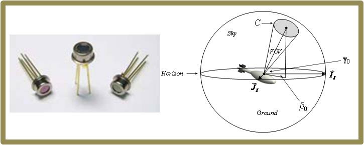
Increasing availability of small, low-cost processing and sensor technology has enabled projectile designers to outfit rounds with full guidance and control capability. However, in contrast to missiles, guided projectiles must withstand extreme loads at launch, use low-cost components, and provide relatively confined spaces for electronics packages. These constraints have posed particular challenges to the development of state estimation systems for projectiles, which must provide accurate state estimates to the guidance system if reasonable impact precision and accuracy is to be achieved. Orientation estimators in particular have not been able to leverage recent advances in inertial navigation technology developed for aircraft and missiles since they are often too expensive for projectile applications or cannot withstand projectile flight environments. As a result, the smart projectile community has turned to low-cost MEMS sensors, magnetometers, and other small robust sensor technology to provide orientation feedback. However, magnetometers and other low-cost sensors can exhibit significant error due to high spin rates and extreme launch accelerations. Thus, there is a continuing need to develop alternative sensors for orientation determination. One such sensor, thermopiles, can be used to detect infrared emissivity gradients between the earth and sky. The thermopile signal can then be used to generate estimates for roll and pitch.
Research
To support projectile state estimation algorithms, a generic, wide field-of-view (FOV) thermopile sensor model that generates realistic thermopile voltage outputs as a function of angle to the horizon and sensor field of view has been developed. The model includes key error sources that pollute these sensor readings and hinder their use for vehicle state estimation. Model results have been compared to experimental thermopile readings with relatively good correlation.
Using an array of thermopile sensors, a recursive least squares (RLS) algorithm has been defined that estimates projectile roll angle and roll rate strictly from thermopile feedback. The estimation algorithm assumes the thermopile signal varies sinusoidally as the projectile rolls, and is robust to unpredictable changes in the Earth’s IR radiance. Example simulations have shown that accurate in-flight projectile roll angle and roll rate estimates can be obtained. Furthermore, results indicate that estimation accuracy improves exponentially as more thermopiles are added to the sensor array.
J. Rogers, M. Costello, D. Hepner, “A Roll Orientation Estimator for Smart Projectiles Using Thermopile Sensors,” Journal of Guidance, Control, and Dynamics, Vol 34, No 3, pp 688-697, 2011. (PDF)
Parafoil Glide Slope Control
Background
Parafoil and payload systems are unique flight vehicles well suited to perform autonomous airdrop missions. These air vehicles are compact before parafoil deployment, lightweight, fly at low speed, and impact the ground with low velocity. The predominant control mechanism for parafoils is left and right brake deflection. When a right brake control input is executed, the right back corner of the parafoil canopy is pulled down by changing the length of the appropriate suspension lines. Canopy changes created by brake deflection subsequently cause predictable changes in aerodynamic loads which is leveraged for control of the vehicle. For most parafoils, deployment of the right brake causes a significant drag rise and a small lift increase on the right side of the parafoil canopy combined with slight right tilt of the canopy. The overall effect causes the parafoil to skid turn to the right when a right parafoil brake is activated. Although a key element of acheiving precise trajectory control, longitudinal control is a more difficult undertaking. Human sky divers use weight shift for both longitudinal and lateral control. By shifting weight fore and aft, glide slope can be actively controlled and permits accurate trajectory tracking, to include very accurate ground impact point control in the presence of relatively high atmospheric winds. New and efficient longitudinal control mechanisms for fully autonomous parafoil and payload air vehicle configurations are needed to enable leap ahead ground impact accuracy improvements.
Research
In order to improve the accuracy of autonomous parafoil and payload aircraft we created a glide slope control mechanism. Rather than using weight shift or symmetric brake deflection glide slope control is physically achieved by changing the longitudinal rigging of the parafoil and payload combination dynamically in flight. The extra degree of freedom of control requires simple rigging changes and the addition of one additional servo actuator to the system. When combined with traditional right and left brake control, glide slope control is an attractive feature for autonomous parafoil and payload aircraft since it allows the flight control laws to directly correct descent rate thus eliminating the need for descent rate estimation and the resulting error induced into the final delivery error.
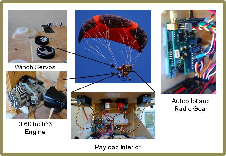
The ability of this system to change glide slope in flight is demonstrated with flight test results for an exemplar micro parafoil and payload system. The micro parafoil and payload system is fitted with a data logger equipped with a sensor suite that contains GPS, accelerometers, gyroscopes, barometric altimeter, magnetometers, and servo position so that the complete state of the payload along with all control inputs can be recorded. These flight test results were subsequently synthesized and incorporated into a 6 degree-of-freedom parafoil simulation and autonomous performance with and without glide slope control was determined. Monte Carlo simulations were performed to predict impact point statistics using only lateral control, and lateral/longitudinal control. Results indicate that a dramatic improvement in impact point statistics is realized with the addition of glide slope control.
A. Gavrilovski, M. Ward, M. Costello, “Parafoil Glide Slope Control Using Canopy Spoilers,” Proceedings of the 2011 AIAA Aerodynamic Decelerator Conference, 2011. (PDF)
Use of Micro Spoilers for Projectile Control
Background
Control mechanisms for smart projectiles must be capable of altering the trajectory of the projectile in such a way that impact point errors induced at launch and in flight can be corrected. At the same time, the physical control mechanism must be rugged to withstand high acceleration loads at launch, small so that payload space is not compromised, and inexpensive for cost considerations. Many different control mechanisms have been developed with these requirements in mind, but all concepts essentially fall into three categories: aerodynamic load mechanisms, jet thrust mechanisms, and inertial load mechanisms.
Research
A new smart projectile control mechanism that uses a grid of micro spoilers has been created. The small micro spoilers are used to induce an aerodynamic force and moment perturbation on high-speed projectiles due to shock wave interaction between the fins, body, and micro spoilers. The micro spoilers are activated in flight in a coordinated fashion to generate maximal control authority.
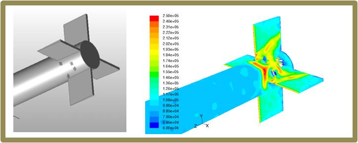
A set of parametric trade studies has been conducted on different micro spoiler configurations uncovering its effects on control authority and accuracy. Prediction of the effects of micro spoiler activation on aerodynamic loads has been produced using computational fluid dynamics analysis while flight dynamic simulation has been based on a rigid body representation. Results to date indicate that very substantial control authority can be generated using this type of projectile control mechanism, particularly at high speeds. With a properly configured flight control law, impact accuracy down to the level sensor errors is possible.
J. Dykes, M. Costello, D. Cler, R. Carson, R. Dillon, “Use of Micro Spoilers for Control of Finned Projectiles,” Proceedings of the 2010 AIAA Atmospheric Flight Mechanics Conference, Toronto, Canada, 2010. (PDF)
Gust Response of Micro Rotorcraft
Background
In the late 1960’s and early 1970’s, the CIA created the Dragonfly aircraft which was an innovative aircraft based on a dragonfly. The constructed prototype was the first flight of an insect-sized machine. A laser beam steered the dragonfly and a watchmaker on the project crafted a miniature oscillating engine for wings beat motion, and an internal fuel bladder carried liquid propellant. Despite the incredible ingenuity that went into the design of this machine, the aircraft was uncontrollable in very lights winds. Ultimately, the gust problem killed the CIA dragonfly project in 1974, and the basic problem of micro air vehicles flying effectively in the presence of wind gusts remains an open problem to this day. Seemingly benign air environments can appear gusty to a small hovering craft due to fans, air conditioners, open windows, etc. Even indoors in rooms without air conditioners and open windows, narrow hallways can create adverse flow conditions simply because aircraft near a wall will have its vortices on one side interacting with that wall asymmetrically.
Research
With the advent of small electronics available today, including sensors, actuators and microprocessors, it may well be possible to control micro air robots in indoor and outdoor gusty conditions. Unfortunately, while it is qualitatively known that micro air vehicles struggle to fly in gusty conditions, micro flyers performance in gusty conditions is not known quantitatively. Moreover, key vehicle and flight control system parameters that drive the performance of micro flyers in gusty wind conditions are not known.
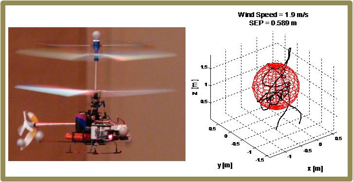
An experimental study was performed to quantify the performance of a micro coaxial helicopter in realistic wind conditions. The experimental study evaluated different representative scenarios including: hover, forward flight, and landing on the edge of a rooftop. Each scenario was flight tested in nominal no wind cases and different wind levels. A synthetic wind generation system was used to create wind disturbances, and digital anemometers were used to measure wind magnitude and velocity at discrete spatial points. A motion capture system was used to measure vehicle position and attitude during flight tests as well as provide feedback for a conventional autopilot. Results show dramatic performance degradation in all wind environments. Flight observations reveal the micro coaxial helicopter could successfully operate in light winds with magnitudes of less than 2 m/s.
S. Zarovy, M. Costello, A. Mehta, G. Gremillion, D. Miller, B. Ranganathan, J. Humbert, P. Samuel, “Experimental Study of Gust Effects on Micro Air Vehicles,” Proceedings of the 2010 AIAA Atmospheric Flight Mechanics Conference, Toronto, Canada, 2010. (PDF)
Movie: Autonomous Flight with No Wind
Movie: Autonomous Flight with 2.0 m/s Gusts
Wind Fin
Background
Two configurations dominate the wind turbine marketplace, namely the horizontal axis wind turbine (HAWT) and the vertical axis wind turbine (VAWT). The rotation axis of a HAWT machine is horizontal with the rotor system supported by a tower. Tall towers typical of HAWT designs provide the machine with access to high winds and therefore more energy production potential. These designs require a means to turn the rotor into the wind such as a weather vane or yaw control. The axis for VAWT machines is vertical, and many different configurations have emerged such as the Darrieus wind turbine, the Gorlov helical turbine, the Giromill, and the Savonius wind turbine. VAWT configurations are typically less costly to construct, but often suffer from low starting torque requiring an alternative power source for starting. Both HAWT and VAWT configurations are not without problems. Due to the elevated nature of HAWTs, maintenance is more time consuming than if the turbines were located on the ground. Due to the fact that HAWT and VAWT configurations employ rotor system power extraction, harm to birds is a persistent issue and limits deployment of these systems near avian habitats. While aesthetics is a highly subjective matter, conventional HAWT and VAWT configurations are often viewed as aesthetically unpleasing.
Other methods to extract energy from atmospheric winds have previously been identified, but are largely uninvestigated. The Wind Fin configuration has a vertical, aerodynamic, oscillating structure which generates motion from atmospheric winds through aerodynamic flutter phenomena. Aerodynamic flutter is well known in the aircraft community and is carefully avoided during design. Operation of the Wind Fin configuration is based on flutter where relatively low atmospheric wind inputs generate relatively large motion outputs. The Wind Fin system has three major components: a mast, a vertical hinged aerodynamic panel, and a power extraction system. The mast anchors the structure and also serves as a pivot axis for the vertical, hinged wind panel. The vertical hinged panels are attached to the mast by a sleeve, which allows the panel to swing freely about the mast. This aerodynamic panel automatically orients itself downwind and responds readily to wind with an oscillating motion. The panel’s oscillating action is self-starting and self-sustaining in the wind and needs no mechanical assist. The power extraction system is attached to the mast so that it is not affected by wind direction. The reciprocating motion of the hinged panel drives a concentric shaft that turns two stacked, opposing, overrunning clutches. These clutches convert oscillating motion to continuous motion and, in turn, drive a bevel gear that turns a generator, producing electricity.
Research
In order to understand the energy extraction potential of the Wind Fin concept, a dynamic model of the Wind Fin has been created and subsequently exercised. The dynamic model is used to predict system limit cycle behavior. Parametric trade studies have been performed to identify promising design configurations to maximize atmospheric wind energy extraction. Since the plunging and pitching motion is not imposed, but rather generated by the interaction of the aerodynamic forces on the system, valuable relationships between performance and physical parameters have been developed.
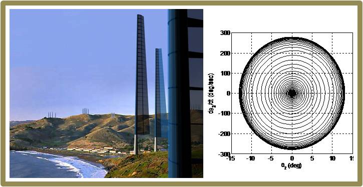
Results to date show that the output power strongly depends on the stiffness and damping in the joints of the system, as well as the mass of the components. While the geometry and operation of the Wind Fin is far different from horizontal axis wind turbines, the power output is within the same range. This wind energy extraction concept shows promise, particularly for applications where the wind mass flows along a rectangular cross section.
V. Manivannan, M. Costello, “Wind Energy Extraction Using a Wind Fin,” 2010. (PDF)